Collins ARC-38/RT-311, ARC-38A And 618S1Transceiver
Once upon a time all aircraft HF radios worked within a fixed group of one or at the most a couple channels, If you wanted to change channels in flight it required a radio operator or at least one member of the crew be trained on how to tune and load the transmitter, or living with a group of fixed channels that were set up pre flight. The one day Collins introduced the 618S-1 The first true auto tune transceiver, a radio that can tune the driver, PA and antenna by itself. this radio was completely automatic and this meant you no longer required a separate radio operator. other radios came latter The TRC-75, 618T series and many improved HF automatic transceivers but the 618S1 was the father of them all. Shortly after the introduction of the 618S the next in the series was developed, the RT-311/ARC-38 unlike the 618S that used a 144 channel crystal deck the 38 used a SMO (Stabilized Master Oscillator) that provides 35,000 possible channels. The SMO uses a Collins PTO and a way complicated mixing system to provide all the channels.
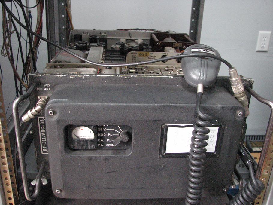
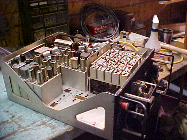
RT-311/ ARC-38 Transceiver
The Remote control (C-1398/ARC-38) provides control of all the radio functions including setting the memory drum for the twenty preset channels and the setting book. unlike the 618S head the 38 gives you separate AF and RF gain controls, two selection CW receive bandwidths ( narrow and sharp) and a CW send and standby switch unlike the 618S that kept the dynamotor running the entire time you were in CW
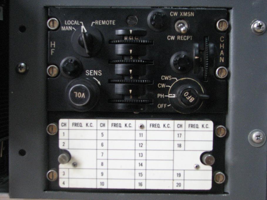
C-1398/ARC-38
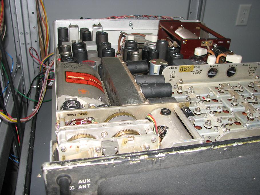
Their is a smaller head that provided just the mode, volume and the twenty preset channels that would be located in other parts of the aircraft. The SMO assemblies can be seen in the next two pictures. Their is a mechanical display on the front of the SMO but it dose not match the settings on the remote head and can only be used for seeing the frequency of the radio in band three.
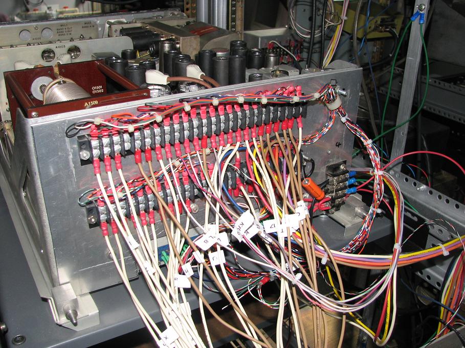
The proper rack rails are almost imposable to find so I have manufactured my own. the two big plugs on the bottom of the radio are fairly standard and two were found on a old HP scope that worked well and then their is the plate the same size as the back of the radio that has the plugs and the terminal strips attached. the new back adapter will not allow you to operate the radio with the case on but like seeing all the servos work so that's not a problem.
The 618S1 Transceiver
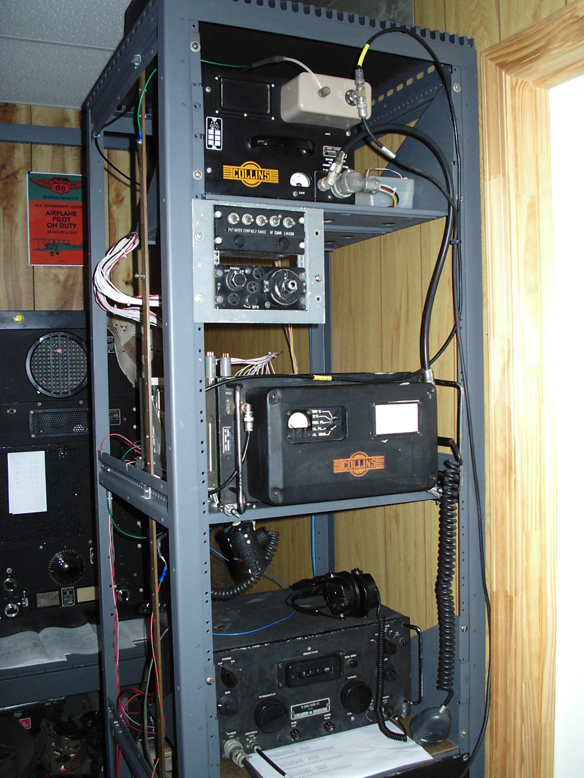
This is my 618S1, a radio many do not like due to the fact that it is crystal control. It featured 144 crystal channels using a signal crystal for both receive and transmit and was AM and CW only. this radio came with about 100 crystals installed with common channels like WWV at 2.5, 5.0, 10.0 and 15.0 Mc, CHU in Canada on 7.35Mc and the old international maritime distress frequency on 2.182 Mc, the radio is in a full size equipment rack with a companion ARR-41 receiver, 28 volt 15 Amp power supply and a 250 volt receiver, bias supply 250 volt and 700 volt plate supply.
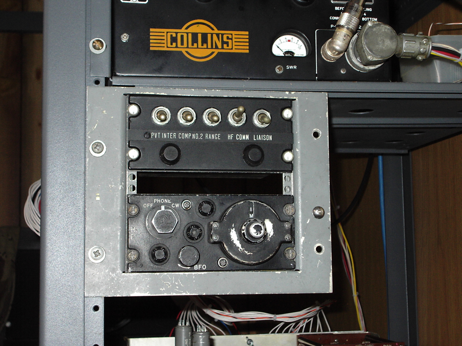
At long last, the correct control head!
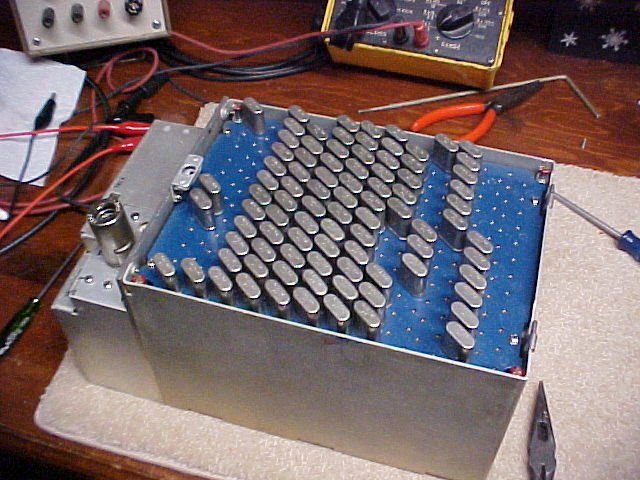
the 144 channel crystal deck and its location inside the 618S chassis. the radio uses ten wires to select any of the 144 channels and they are arranged in groups of 24 each with a different letter prefix for each group. Their are no stored presets or memory's for the tuning the two internal servo sections in the radio tune the radio every time the channel is changed. The radio dose work in four preset bands and crystal location determines what band the radios output will be. all crystals are in the two to three megahertz range.
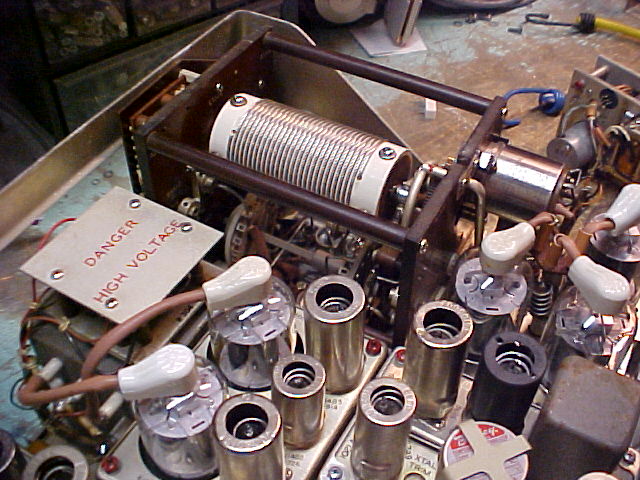
The AM modulator and modulation transformer. the 618S1 is plate modulated with a relay that bypasses the modulation transformer in the CW mode. The radio also features a two stage audio processor that limits frequency response and clips peaks to prevent over modulation or splatter.
I will include additional information about crystal selection, bands and pin connections at the bottom of the page.
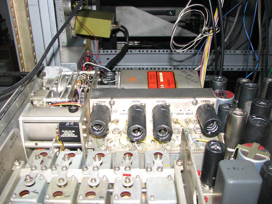
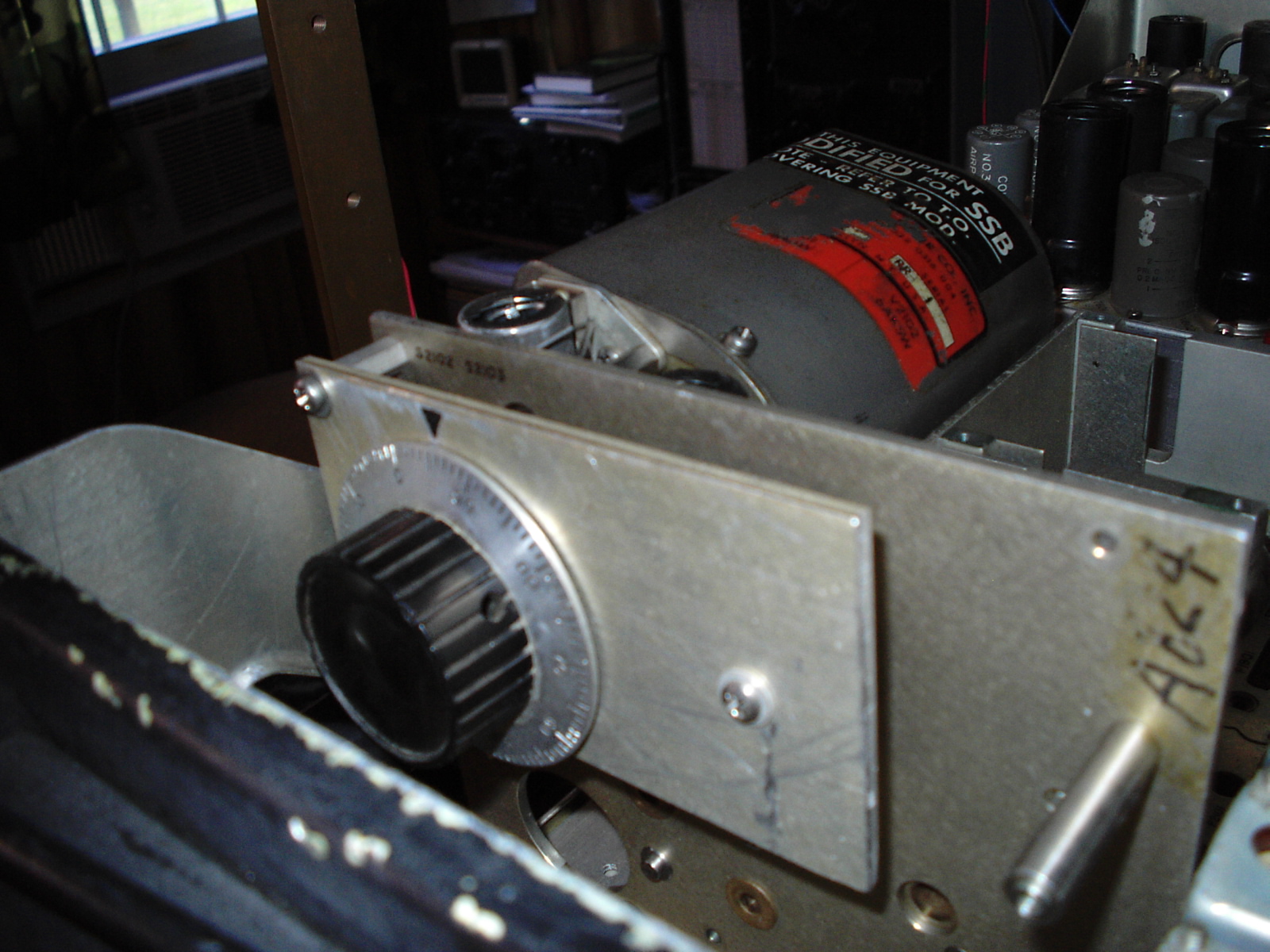
Trying to find crystals has turned into a real problem, so I decided to gut the SMO deck from a ARC-38A and use its PTO to drive the 618S1 The PTO has the same output as the crystal bank and the bank selector on the control head allows you to select the band the radio is operating in so now I can cover any channel in the 2 to 25 MHz range of the radio. Much time has been spent on 7.290 and 3.885, have not had a QSO on 14.236 but hope to soon. Couple pictures of what the modified PTO deck look like.
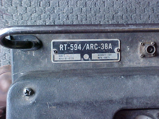
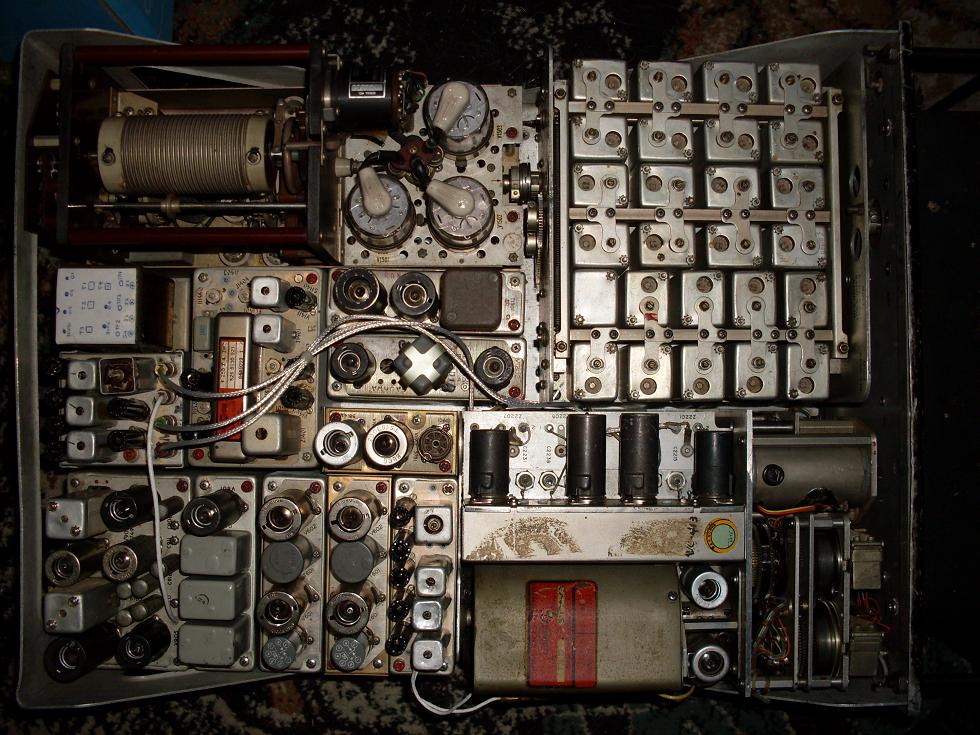
The RT-594/ARC-38A
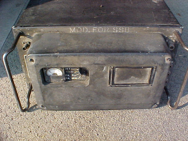
The 38A uses the same PA, Receiver audio, control relay, PA, variable IF/drive deck and two sub servo systems as the 38 and 618S series of radios. Many parts like the servo, PA amplifier, RF/IF deck , relay and audio amplifier are the same but have different part numbers, also all radios modified for SSB have "Modified for SSB" stamped on them including things like the receiver audio amplifier and relay module.
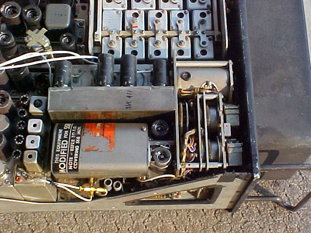
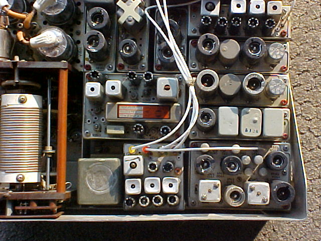
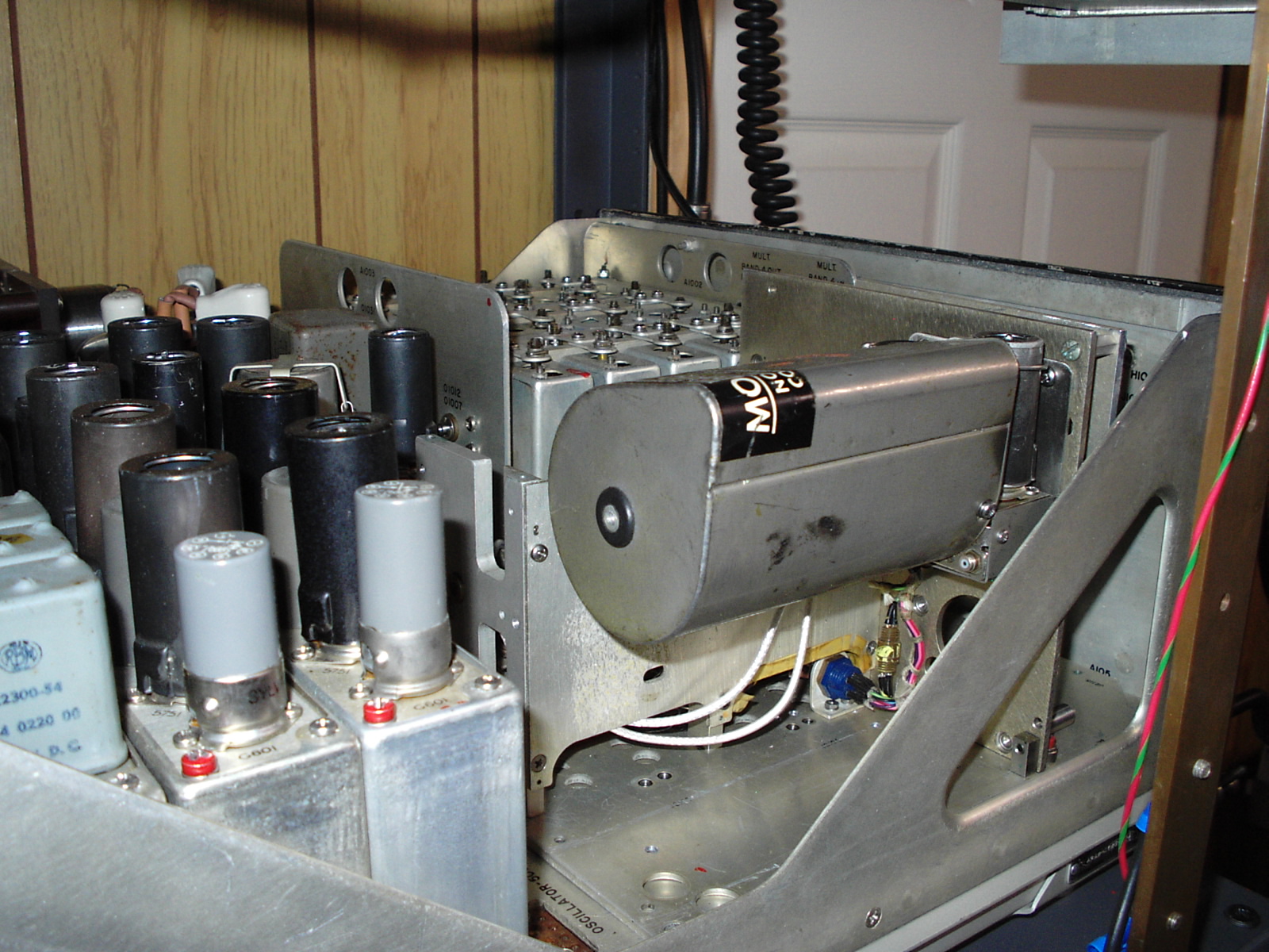
The stabilized Master oscillator has several wires that snake out of it to the IF and SSB audio deck, also you can see the different SSB modulation decks located between the PA and IF deck. Although the radios were originally built by Collins the modification to the 38A standard was carried out by RCA, this results in a very complicated radio. I have not attempted to get a 38A into operation and the one 38A I had gave its life to restore the 618S and 38 that I have in operation.
The 618S and ARC-38A from Down Under
For the longest time I thought all 618S1-4 series radios were removed from service and replaced with ARC-38A series radios built for SSB operation. although I saw references to a SMO assembly and a 618S that had a Stabilized Master Oscillator system did not thin it really existed. Then I got these pictures from Brad Latta showing the rear SMO 618S transceiver
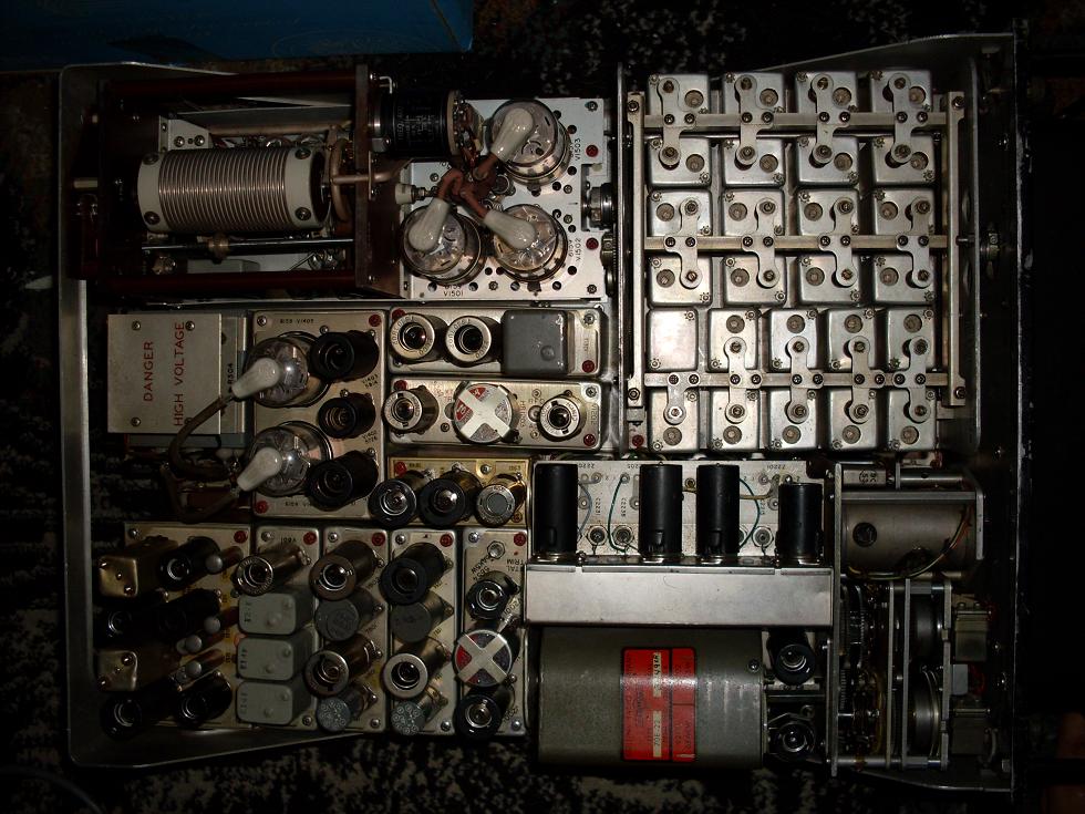
The first picture shows a regular modified ARC-38A SSB radio, they always appear to be a jumble of additional wiring and connectors and a odd mix of sub miniature tubes and the like. The second picture shows the SMO 618S, very clean almost identical to a regular 618S with the AM modulator deck and AM/CW receiver IF deck. Too bad its on the other side of the world. A update! in early 2009 at Dayton I found a complete ARC-38, 180L Antenna tuner and C-1398 Head, That's the radio that appears at the top of the page so now I know that their are at least two ARC-38 not A series in existence!
The 180L Automatic Antenna Tuner
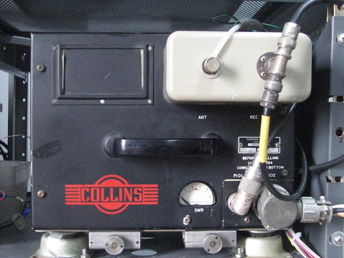
This tuner was a integral part of both radios. Its provides the 50 Ohm load to the transceiver while connected to the aircrafts 40 to 100 foot wire antenna and also provides the T/R switching for the transceiver, this allows the receiver to connect to the antenna before the tuner. The antenna tuner uses one servo system to tune the load. All three servo systems antenna, power amplifier and IF/driver use the same type of servo systems. a discriminator produces a DC output that reads zero volts at resonance. this output is feed to a AC chopper that works at 400 cycles and feeds a amplifier that produces 120 volts AC at 400 cycles that changes its phase in proportion to the input voltage, this feeds one set of windings in a servo motor and the second set of windings is feed a reference 120 volts 400 cycle and the motor will turn in the direction of the variable phase input. The mechanical choppers, two in the radio and one in the tuner make a huge amount of noise when in operation fortunately you can kill the 120 volt AC supply to the servo sections when the radio is tuned so you don't have to hear it constantly.
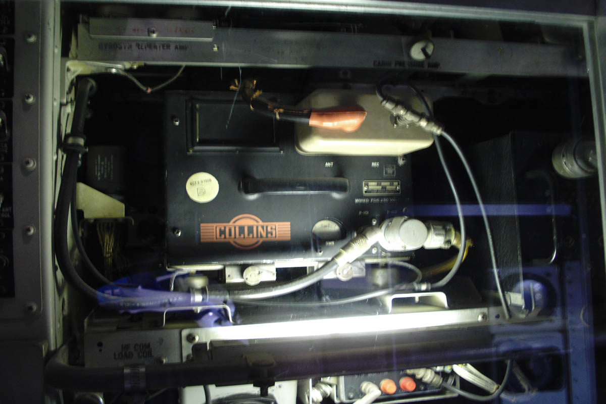
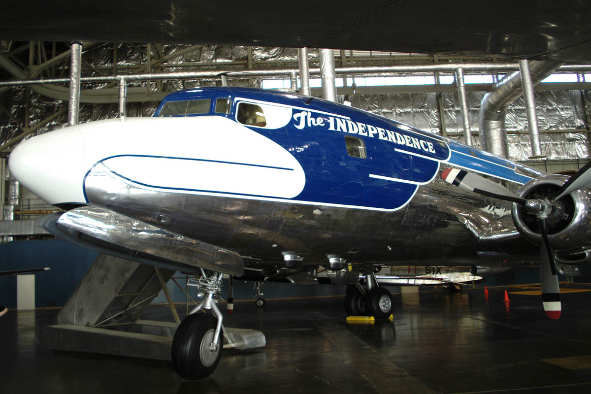
This is one of two 180l tuners installed in the "Independence" a Douglas VC-118 (military version of the DC-6) that was Truman's presidential airplane and later served as a VIP transport until retired in 1965
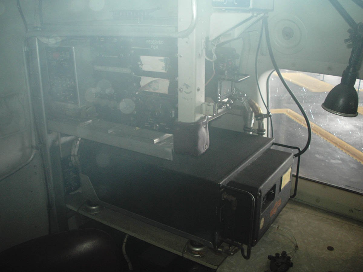
This is a 618S1-4 installed with the local control directly above at the navigators station. The 180L tuner for this radio ( above) is located just forward in a avionics bay. their is a ARC-38A directly across from this radio with another 180L above it and the control heads being in the cockpit center consul and above the 618S head on the navigators panel.
Technical stuff:
AN\ARC-38 Frequency Settings:
Frequency Switch Drum
3880.0 KC B1 2 A 6 B FG KL OQ UWX
3885.0 KC B1 2 A 7 B FG KL QS UWX
3890.0 KC B1 2 A 7 B FG KL QS UWX
5000.0 KC B1 5 A 0 B FI KN OS UWX
7160.0 KC B3 8 A 2 B EF LN PQ UXW
7280.0 KC C1 0 A 3 C FG JN QR UXW
7285.0 KC C1 0 A 3 C FG JN QR UYZ
7290.0 KC C1 0 A 4 C FG JN OR UWX
7295.0 KC C1 0 L 4 C FG JN OR UYZ
7850.0 KC C1 6 A 0 C FG JL OS UWX
10.000 MC C3 7 A 5 C FI KM PS UWX
14.286 MC D1 0 S 1 D FG JN OP TVX
15.000 MC D1 3 L 7 D FG LM PR UYZ
Displays on SMO are only correct in the "C" band, local controls knobs are 500 KC for top, second 50 KC third 0.5 KC and forth 5.0 KC per number.
Band A= 2.0 to 3.75 Mc, Band B= 3.75 to 7.25 Mc, Band C= 7.25 to 14.25 Mc and Band D= 14.25 to 25.0 Mc
618S1 Information:
All Crystals Oscillate from 1.75 to 3.5 Mc
Channel = f – 0.250 / band multiplier
Multiplier Band 1 x1 Band 1 = 2.0 to 3.75 Mc
Band 2 x2 Band 2 = 3.75 to 7.25 Mc
Band 3 x4 Band 3 = 7.25 to 14.25 Mc
Band 4 x8 Band 4 = 14.25 to 25.0 mc
Relays
K-801 Sequence relay ON while changing channel or band. OFF when on channel
K-802 ATU Centering relay On while changing channel OFF when radio is on channel
K-803 Mode relay On in CW Off in AM
K-804 Keying relay On in transmit Off in receive
Rear connectors
K-N Band Switch (pins 19-20-21-22 on 301) A-F Crystal bank select (pins 1-2-3-4-6-8 on 302) R-W Channel select (pins 5-7-9-11-13-15 on 302)
P301 1- +600vdc transmitter plate
3- 115vac blower
4- 115vac for servos
5- -50 bias for modulator
6- Audio output (same as front phones)
7- CW / AM switch
8- Microphone input (same as front microphone)
9- -65 bias for PA
10- BFO control (10K)
12- PTT
13-
14- +250vdc receiver and exciter
15- +250vdc transmit
17- Ground
18- Ground
20-
21- 6vac side tone
22- +28vdc
23- +28vdc
27- Ground for audio
28-
29-
31- Keying interlock
P302 10- RF gain control (5K)
17- Ground
18- Ground
19- Band 3 select
20- Band 4 select
21- Band 1 select
22- Band 2 select
23- +28vdc
24- +28vdc
28- Dynamotor interlock
30- Side tone out
31- Side tone in
YouTube - ARC-38 YouTube video of ARC-38 in action!
Return to main page Rays Web Page
july 2010