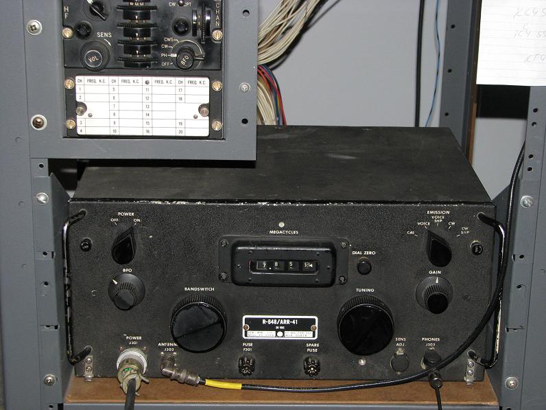
AN/ARR-41 Modifications
Warning:
Vacuum tube radios produce potentially lethal voltages! No one should attempt to restore or modify anything without proper knowledge of that working environment. The modifications outline below result in B+ being exposed on the top side of the chasse and this radio must not be operated without the protective cover!
Radio Receiving Set AN/ARR-41 is a super heterodyne receiver covering from 190 to 550 kc and 2 to 25 Mc. Double conversion is used in all bands except band 2. The 2 to 4 megacycles band which is single conversion. Two r-f stages, three if stages and three audio stages with a sensitivity of at least 100 mill watts audio output for 5 microvolt input and selectivity obtained through use of one of the two mechanical Filters in the I.F. circuit. Unitized construction is employed, greatly simplifying trouble-shooting and maintenance operation.
Originally B+ (250 Volts DC) was provided by a dynamotor with the radio being powered by 28 Volts DC from the aircraft it was used in. To my knowledge there was never an AC 60 cycle or 400 cycle version of the radio built. All AN/ARR-41 receivers were built with the dynamotor assembly and for DC operation.
In addition to this the filament string, power control and fuse circuit are all on the 28 volt DC distribution. On the front panel is a choke and filter capacitor used in cleaning the DC input to the radio. Many of the receivers on the market today have been modified to operate on AC by removing the dynamotor, installing transformers and changing the incoming wiring to distribute AC into the set and power the radio. If you want to restore the radio to its original condition you will need to locate a replacement dynamotor (250 VDC@100Ma) or look at a different method of developing the B+ voltage
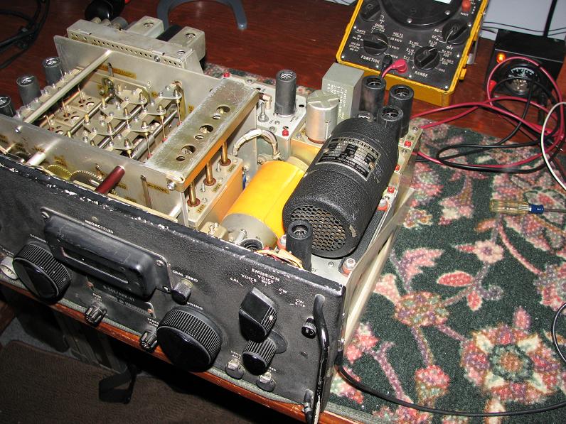
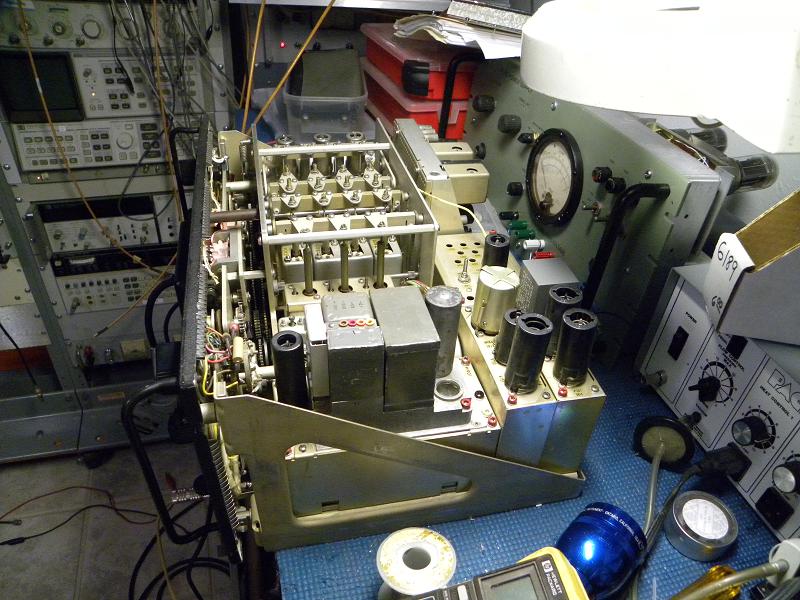
Ham built AC power supply on Dynamotor deck
Although I already have an original dynamotor deck for my radio I decided that I would like to build up a solid state inverter system in order to remove the dynamotor deck and have something that was quiet to operate and would not produce vibrations. After locating a second dynamotor chassis that had a home built AC power supply I striped down this frame and kept the original VR tube regulator and other voltage dividers located on this frame and then started looking for a suitable inverter circuit. Being that I wanted to use military components I decided to use the DC to DC power inverter from a ARC-73 or a ARC-51 being that Bothe are small and easy to work with. I found a source for DC to DC converters from ARC-51 sets that had been demilled by being cut into with a torch for only $10 each and ordered a couple.
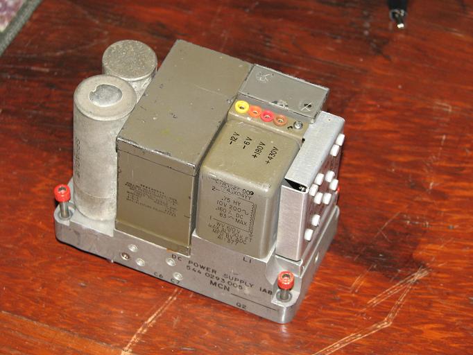
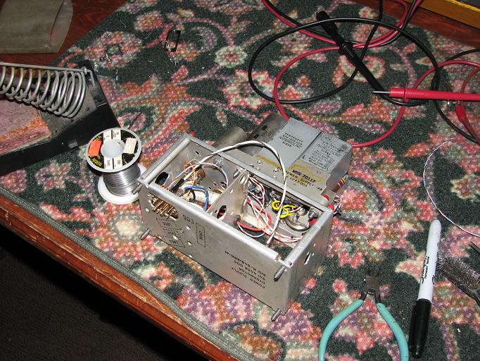
Original ARC-51 DC to DC converter Installation of DC to DC converter on Dynamotor deck
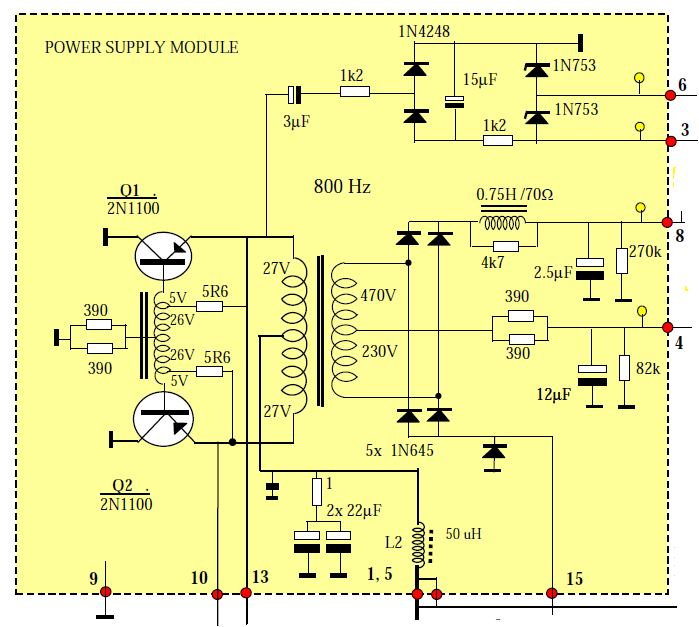
Schematic of ARC-51 DC to DC Converter. The biggest changes to the inverter is to remove all unused components for the bias supplies and change the secondary of the inverter transformer from 470 volt full wave bridge to a full wave with grounded center tap that now provides 230 volts for the B+, I also reworked the filters for a capacitor input filter from the old 470 volt choke input filter.
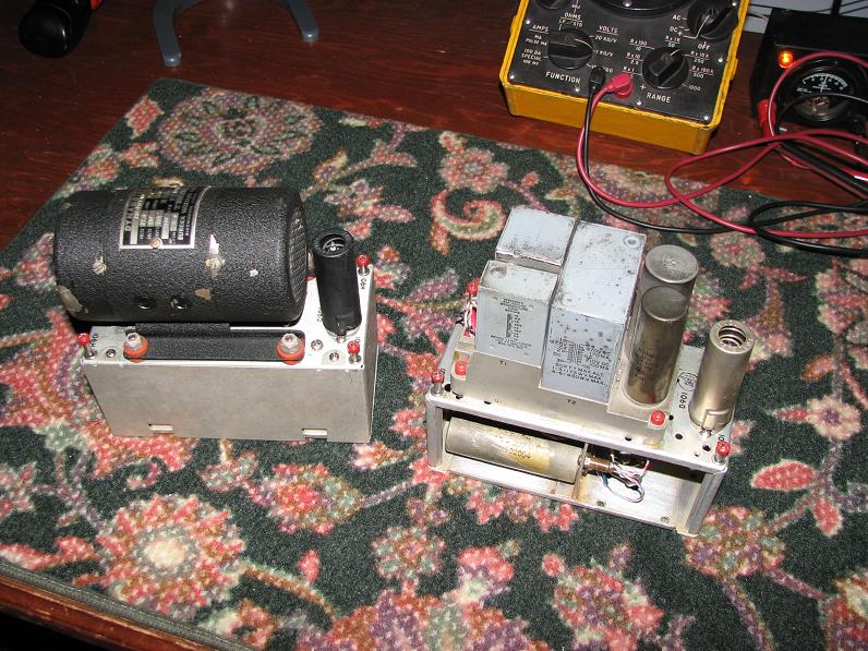
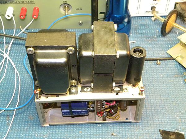
Pictures of the two finished power supplies side by side
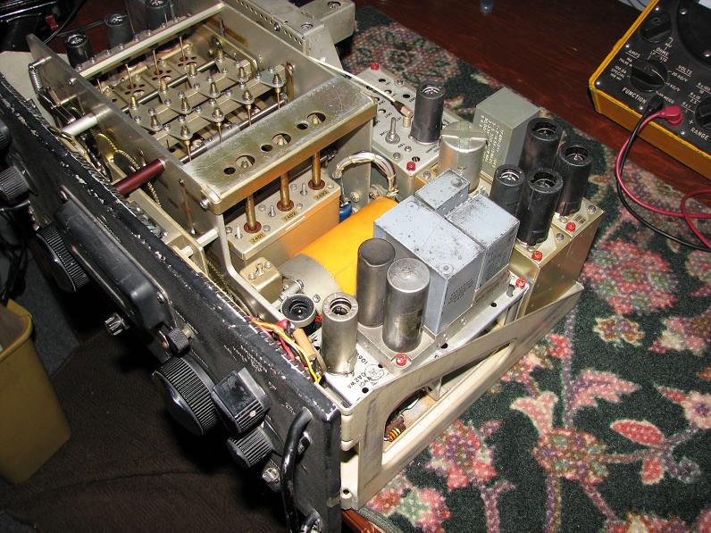
Power supply installed in the receiver, yes! the cover still fits.
Another receiver modified the same way from a collector down in Texas, in this case he kept the DC to DC converter all stock and installed a plate with a connector on the Dynamotor deck.
The receiver is a good receiver to use for AM or CW operation. It was built just before the deployment of SSB and lacks a product detector or AGC system in the CW mode so its SSB performance is not that good, also it has the standard arraignment of the time where the gain control will work as a AF gain control in AM with the RF gain controlled by the AVC system and the gain control becomes a RF gain control with AF gain full up in the CW mode, all right for AM and CW but not so good for SSB. Using a DC to Dc converter in the power supply avoids the whole problem of the noise of the dynamotor and the vibration of that unit. The slight reduction of the B+ voltage appears to have no noticeable effect on the receiver's performance. Being that I operate almost entirely AM the receiver has been and will continue to be a good second receiver when I use the AN/ARC-38 located just above it.
Trivia!
The original dynamotor is a Eureka Williams 231-0103-001 250 Volt DC @ 100 Ma output, The original number for the Dynamotor Power supply is 541-4458-005
Nov 2011