
Motorola AN/URC 110, 101, 104 and 200
The Motorola URC 100 series of transceivers started with the deployment of the PET-25 (Portable Emergency Transceiver) in 1978, that was replaced with the URC-101, a VHF/UHF transceiver the same size as the PET. The PET can be recognized by being the only radio of the family with a small round meter located on the front of the radio where the "retransmit" connector is today. The URC-104 is a 101 with the VHF transverter replaced with a low band VHF transverter to cover the tactical range of 30 to 70 MHz and the URC-110 replaced the URC-101 with additional memory presets, elimination of the leaky battery in the control head and best of all the ability to move in 5 kHz steps, a real plus for operations on the Ham bands. Their are other variations like the URC-100 that no one has ever seen and the very strange URC-112 with a 2.5 kHz spacing and a almost useless up shifted VHF band but the 101 and 110 appear to be the most common on the surplus market. The URC-110 was replaced by the URC-200 that's still in current production by General Dynamics and their is also a PET-2000 that is a Civil version of the URC-200 that brings back the portable emergency designation.
PET-25 URC-101
URC-110 URC-200
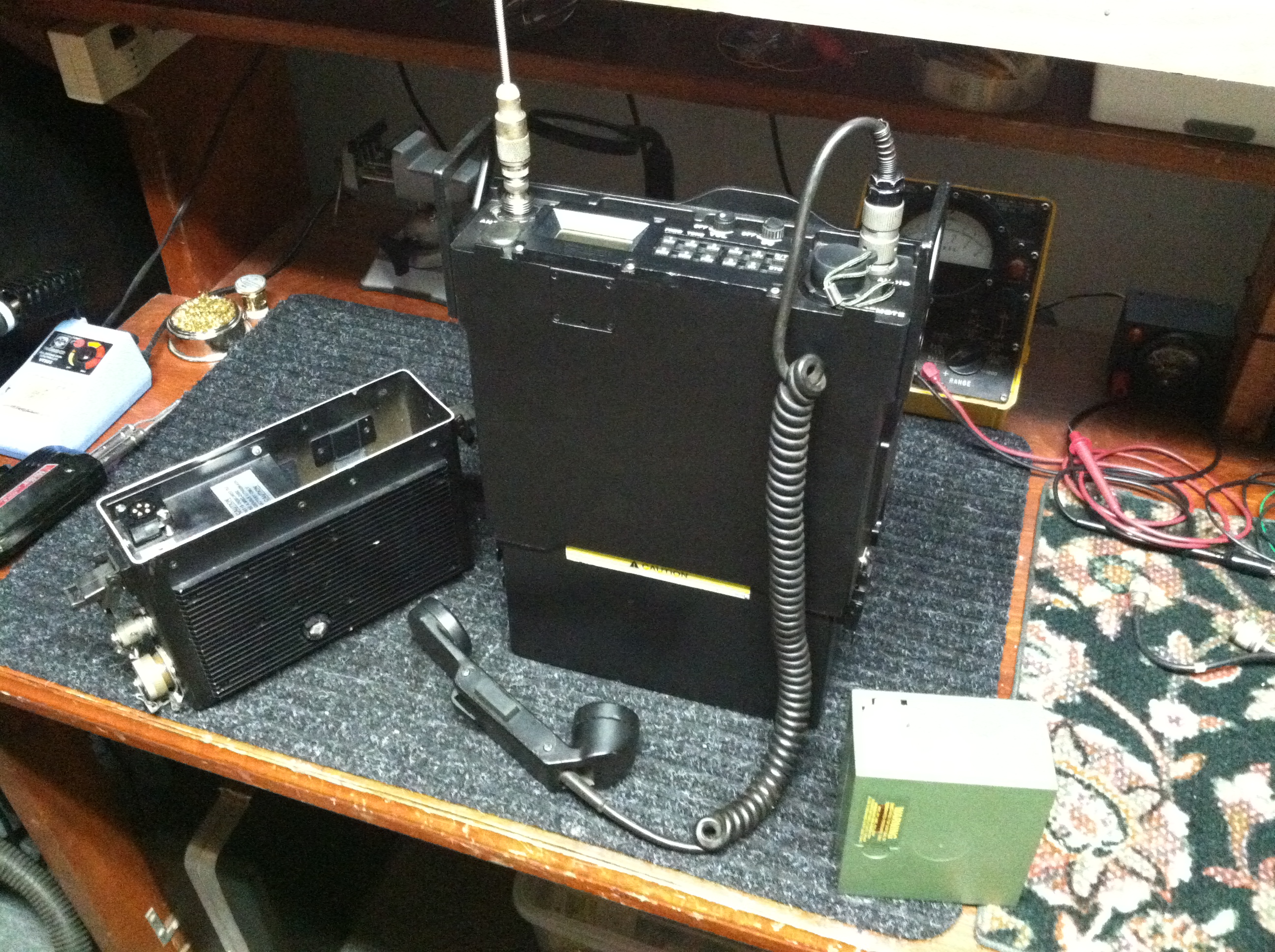
The AN/URC-200 115.00 to 173.995 MHz in 5 KHz steps along with 225.00 to 399.995 MHz AM or FM 0.1, 5 and 10 Watts
and 10 preset channels. The AC/DC power supply is next to it. The Radio uses regular 5590 battery packs.
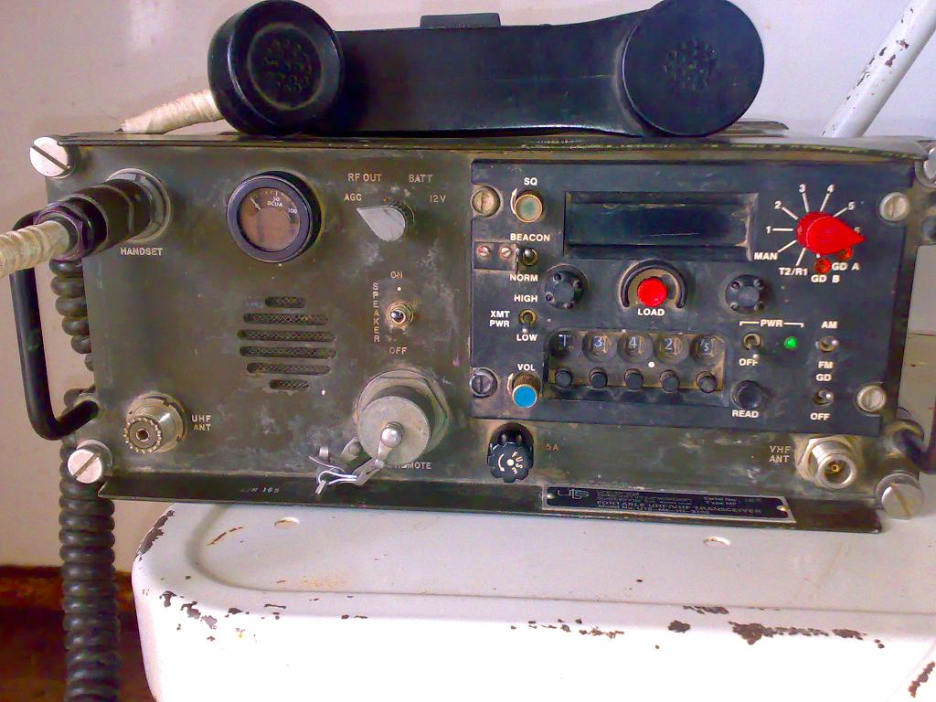
This is a URC-110, a lot like the URC-101 but with one big difference. the 110 tunes in 5 KHz steps, that makes it way more useful on the Ham bands. The VHF range is 116.00 to 150.00 MHz and UHF 225.00 to 400.00 MHz it also has a improved low noise synthesizer and IF optimized for 5 KHz channels. Using the "X Mode" connector on the front of the radio I have used this radio many aspects of packet operation. The X mode connector gives direct inputs and output to the discriminator and modulator. In military life they used a PM-15 adaptive tactical modem.
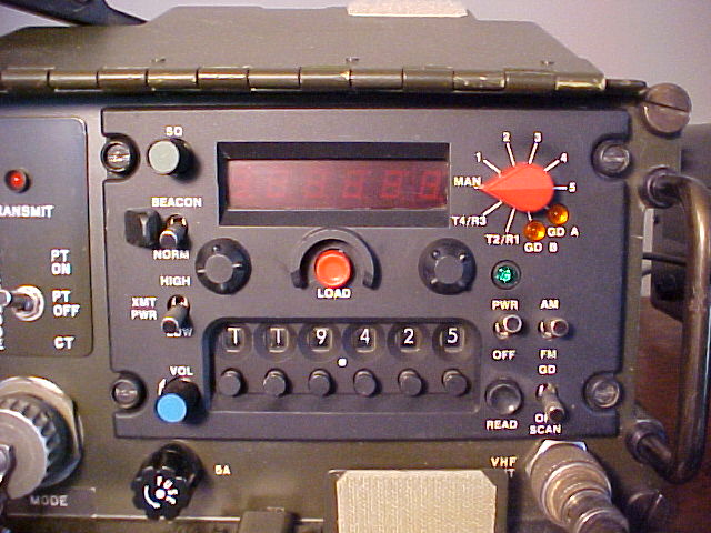
The last row on the frequency selector makes all the difference , also the 110 gives you one additional offset setting in memory. below that is the AM/FM mode switch, you can operate on AM or FM on any of the radios frequencies. below that their is a scan function that will scan guard A and B along with what ever channel the radio is set to and across from all that is the beacon switch that forces the transmitter to continually transmit a yelp signal.

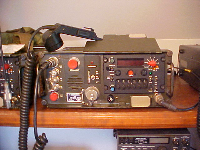
This is a URC-101 it moves in 25 KHz increments, has ten preset channels and has the capability to operate any programmable split. Both 101 and 110 transceivers are rated at 1.5, 5 and 20 Watts output. The power level was always a bit low for Satcom applications so the radios were frequently paired with AM-7175 200 Watt linear power amplifiers.
Power supplies
Their are two different power options for the radio, a universal power supply( PTAD-101) that works from 120/240 VAC or 28 VDC, although I have used one on as low as 12 VDC . They use a internal switching regulator that allows a wide range of inputs. Be aware that if you reverse polarity of the DC input it will short out a protective diode across the DC bus. The radio uses 28 volts DC for everything with a internal switching supply in the radio that provides +12 Vdc and +5 Vdc The DC input to the bottom of the radio is directly applied to the amplifiers and several other circuits so be carful if you don't have the battery box or AC supply!
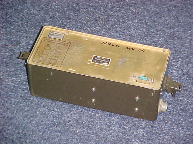
PTAD-101 Power supply
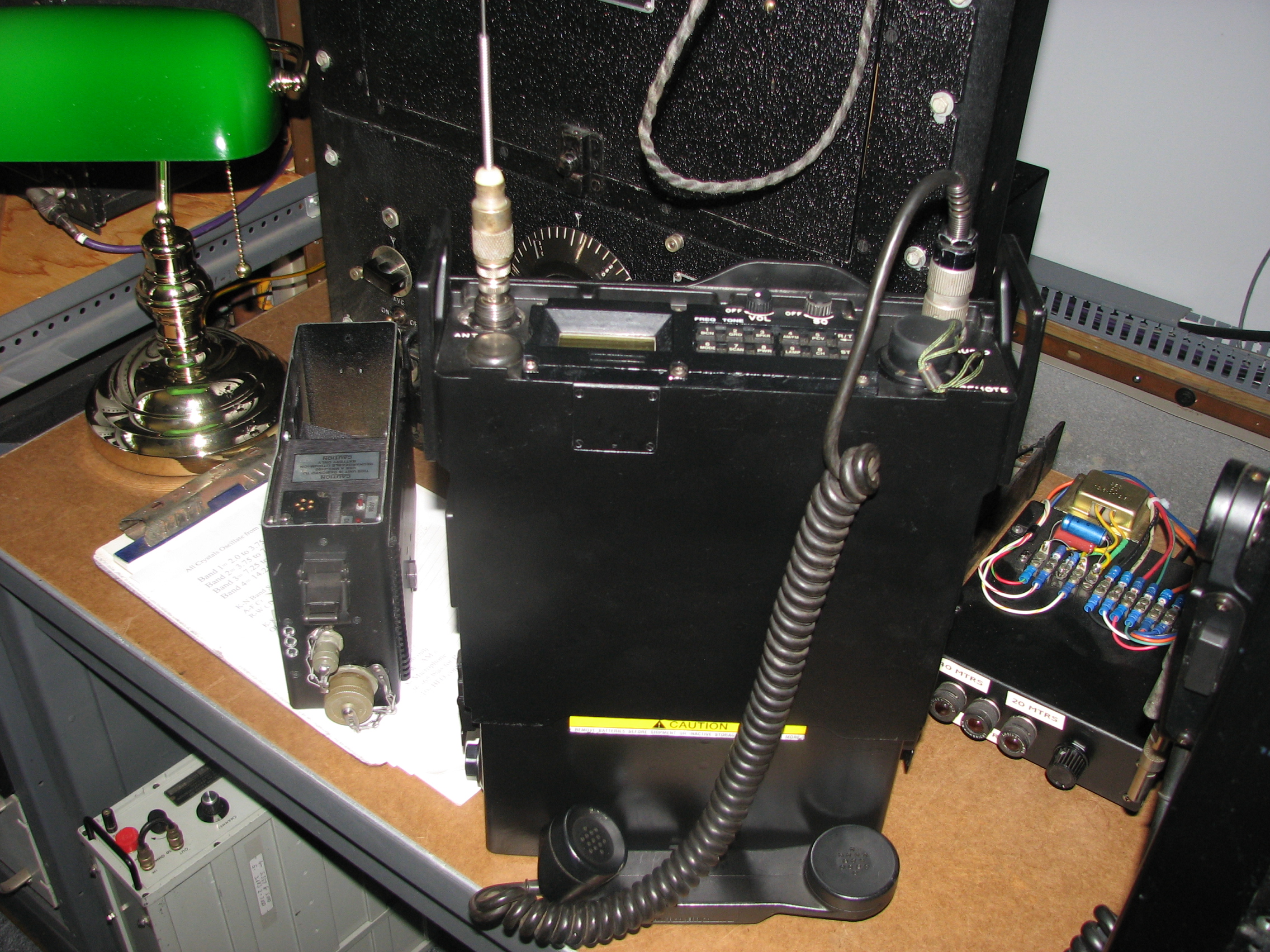
The other options is a dry battery box (PTL-110A) it accommodates two PRC-25/77 dry batteries to get 24 VDC.
I put four 6 volt Gel-Cells and that works for all day. The case has a internal charging circuit that was intended for charging NiCad batteries.
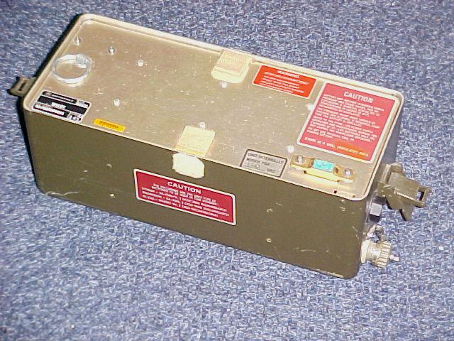
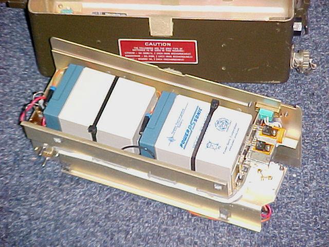
PTL-110A Battery Box
Connectors
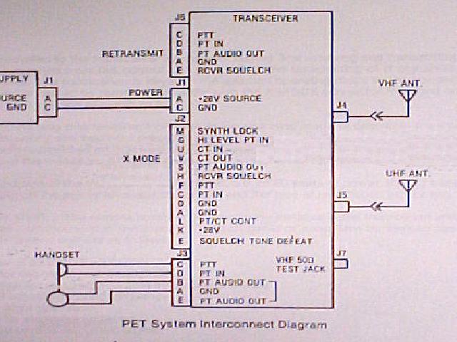
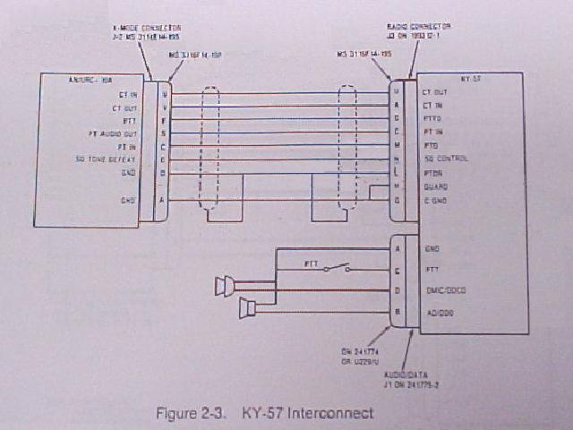
The radio has a wide band audio input and output, originally for use with different voice encryption systems. I use the input and outputs for both 1200 and 9600 baud packet radio. The inputs and outputs are the "CT" connections on the "X" mode connector, just incase you have a KY-57 here is the wiring diagram.
And a close up of the X mode connector
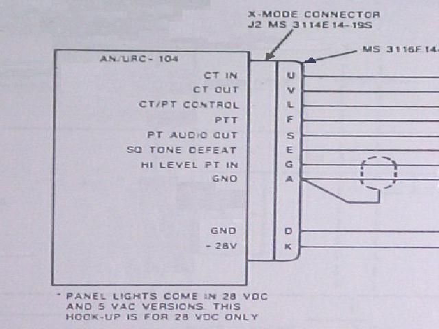
This is the drawing for a URC-104, but the pinout is the same for everything. PET-25, URC-100,101,104 and 110
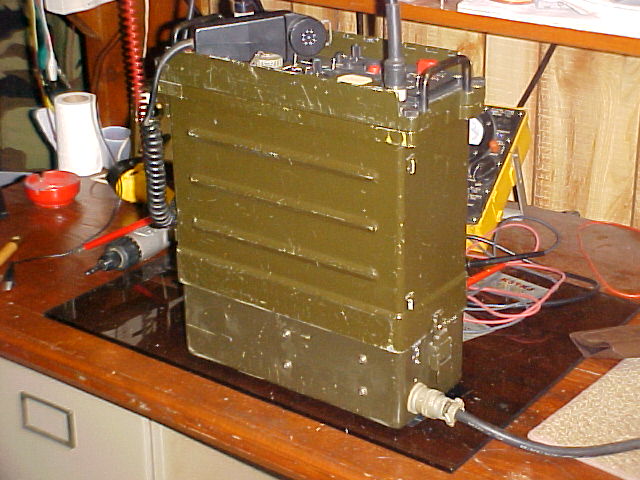
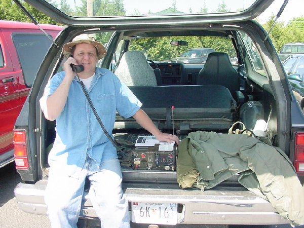
That's me using one at a Hamfest.
Return to "Rays Web Page"
DEC 16